
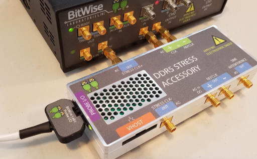
High-speed digital systems depend on clean, stable, and predictable signal transmission. As data rates increase, even a small impedance mismatch, connector issue, PCB defect, or transmission-line discontinuity can affect system performance. Engineers therefore need reliable methods to understand what is happening along a signal path. TDR for signal integrity testing provides a practical way to locate and analyze these problems by examining how electrical signals behave as they travel through cables, traces, connectors, and other components.
What Is TDR and Why Is It Important?
Time Domain Reflectometry, commonly known as TDR, is a measurement technique used to analyze transmission lines and identify changes in impedance. A TDR sends a fast electrical signal into a device or transmission path and observes the reflections that return.
When the signal encounters a change in impedance, part of the signal is reflected. By analyzing the timing and shape of that reflection, engineers can determine where a discontinuity occurs and gain valuable information about its characteristics.
This makes TDR particularly useful during the design, debugging, and validation of high-speed electronic systems.
Why Does Signal Integrity Matter in High-Speed Designs?
Signal integrity becomes increasingly important as digital systems operate at higher frequencies and faster data rates. Signals traveling through a PCB trace or cable can experience reflections, attenuation, crosstalk, ringing, and other distortions.
Poor signal integrity can lead to:
- Data transmission errors
- Timing problems
- Increased jitter
- Signal reflections
- Intermittent system failures
- Reduced communication performance
- Electromagnetic compatibility concerns
A design may appear to function correctly under basic testing but still contain signal integrity weaknesses that become noticeable at higher operating speeds. Detailed measurement helps engineers identify these issues before they become expensive production problems.
How Does TDR Identify Signal Discontinuities?
A TDR works by sending a known electrical stimulus into the transmission path. If the path maintains consistent impedance, the signal continues with minimal reflection. When it encounters a discontinuity, some energy returns toward the measurement instrument.
The time required for the reflection to return provides information about the location of the discontinuity. The amplitude and shape of the reflection provide additional clues about the nature of the impedance change.
For example, engineers may use TDR measurements to investigate:
- PCB trace transitions
- Connectors
- Cables
- Vias
- Solder joints
- Backplane connections
- Package interconnects
- Transmission-line structures
This makes TDR a valuable diagnostic tool for modern electronic hardware.
What Problems Can TDR Reveal?
One of the biggest advantages of TDR is its ability to provide a physical view of the transmission path. Instead of simply indicating that a system has a performance problem, the measurement can help identify where the problem originates.
Common issues that can be detected include impedance discontinuities, open circuits, short circuits, connector mismatches, damaged cables, improperly designed transitions, and unexpected changes in transmission-line geometry.
Engineers can use this information to determine whether a problem originates from the PCB layout, interconnection system, manufacturing process, or another component.
TDR in PCB and High-Speed Interconnect Analysis
Printed circuit boards used for high-speed applications require carefully controlled impedance. Trace width, dielectric material, layer structure, spacing, vias, and connectors can all influence signal behavior.
TDR measurements allow engineers to examine impedance along a transmission line rather than relying entirely on design calculations. This can be particularly helpful when validating prototypes or investigating differences between simulation and physical measurements.
For production environments, TDR can also support quality-control processes by helping identify manufacturing variations that could affect high-speed performance.
TDR and Signal Integrity Debugging
When a high-speed system fails testing, locating the source of the problem can be challenging. Engineers may need to investigate multiple components and interconnections.
TDR simplifies this process by providing information in the time domain. A reflection appearing at a particular point on the waveform can indicate where a discontinuity exists.
This approach can reduce troubleshooting time because engineers can focus their investigation on a specific section of the signal path instead of examining the entire design blindly.
How BitWise Laboratories Supports Signal Integrity Analysis
BitWise Laboratories develops measurement solutions for engineers working with high-speed digital systems. Its expertise includes TDR-based measurements, bit error rate testing, signal integrity analysis, and characterization of high-speed interconnects.
By combining appropriate test equipment with accurate measurement techniques, engineers can gain a clearer understanding of how their designs behave under demanding conditions. BitWise Laboratories helps researchers, designers, and test engineers investigate signal performance and make informed design decisions.
What Should Engineers Consider During TDR Measurements?
Accurate TDR measurements depend on more than simply connecting an instrument to a device. Test setup, calibration, cables, connectors, adapters, and measurement conditions can all influence the results.
Engineers should consider:
- Proper instrument calibration
- Suitable test fixtures
- High-quality connectors and cables
- Appropriate measurement bandwidth
- Controlled impedance
- Device-under-test configuration
- Repeatability of measurements
- Correct interpretation of reflection waveforms
Careful preparation helps ensure that observed reflections originate from the device being tested rather than from the measurement setup.
Can TDR Measurements Improve Product Development?
Yes. TDR can be valuable throughout the product development cycle. During the design stage, engineers can use measurements to validate transmission-line structures. During prototype testing, TDR can help identify unexpected discontinuities. During production, it can support quality verification and troubleshooting.
Using TDR for signal integrity testing can therefore contribute to better design validation, faster debugging, and more reliable high-speed products.
The ability to identify physical discontinuities and impedance variations gives engineers actionable information that can complement simulation and other electrical measurements.
The Growing Importance of Signal Integrity Testing
As technologies such as high-speed networking, advanced computing, automotive electronics, telecommunications, and data-center infrastructure continue to evolve, signal integrity requirements are becoming more demanding.
Design teams increasingly need measurement methods that can reveal subtle problems before they affect system operation. TDR offers a direct way to investigate transmission paths and understand how signals interact with real-world interconnect structures.
Conclusion
Reliable signal transmission requires careful design, accurate simulation, and thorough physical validation. TDR provides engineers with a powerful method for locating impedance discontinuities and understanding transmission-line behavior.
For organizations developing high-speed electronic systems, BitWise Laboratories offers specialized measurement capabilities that can support signal integrity investigation, debugging, and validation. By incorporating precise TDR measurements into the engineering workflow, teams can identify problems earlier, improve design confidence, and develop more dependable high-speed products.